Impeller, Diffuser and Scroll — How a Centrifugal Compressor Stage Works
A technical training walkthrough of the three key components in a centrifugal compressor stage — with the original training diagrams.
Every centrifugal (turbo) compressor stage is built around three components in the flow path: the impeller, the diffuser and the scroll. Understanding what each one does — and where the losses come from — is the fastest way to judge why a machine loses pressure, surges, or needs a replacement impeller. This page is a walkthrough of a technical training presentation on impeller, diffuser and scroll function, page by page.
1. What each component does
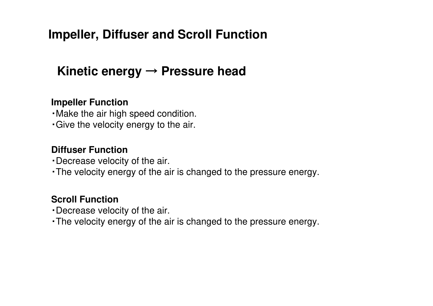
The impeller is the only component that adds energy to the gas: it converts shaft power into gas velocity (kinetic energy). The diffuser slows that high-speed flow down, and the scroll (volute) collects it and guides it to the discharge — in both, the velocity is converted into pressure. That is why a worn or damaged impeller hits the whole machine, while a distorted scroll mainly shows up as inlet distortion and surge margin loss.
2. Stage design and where the losses are
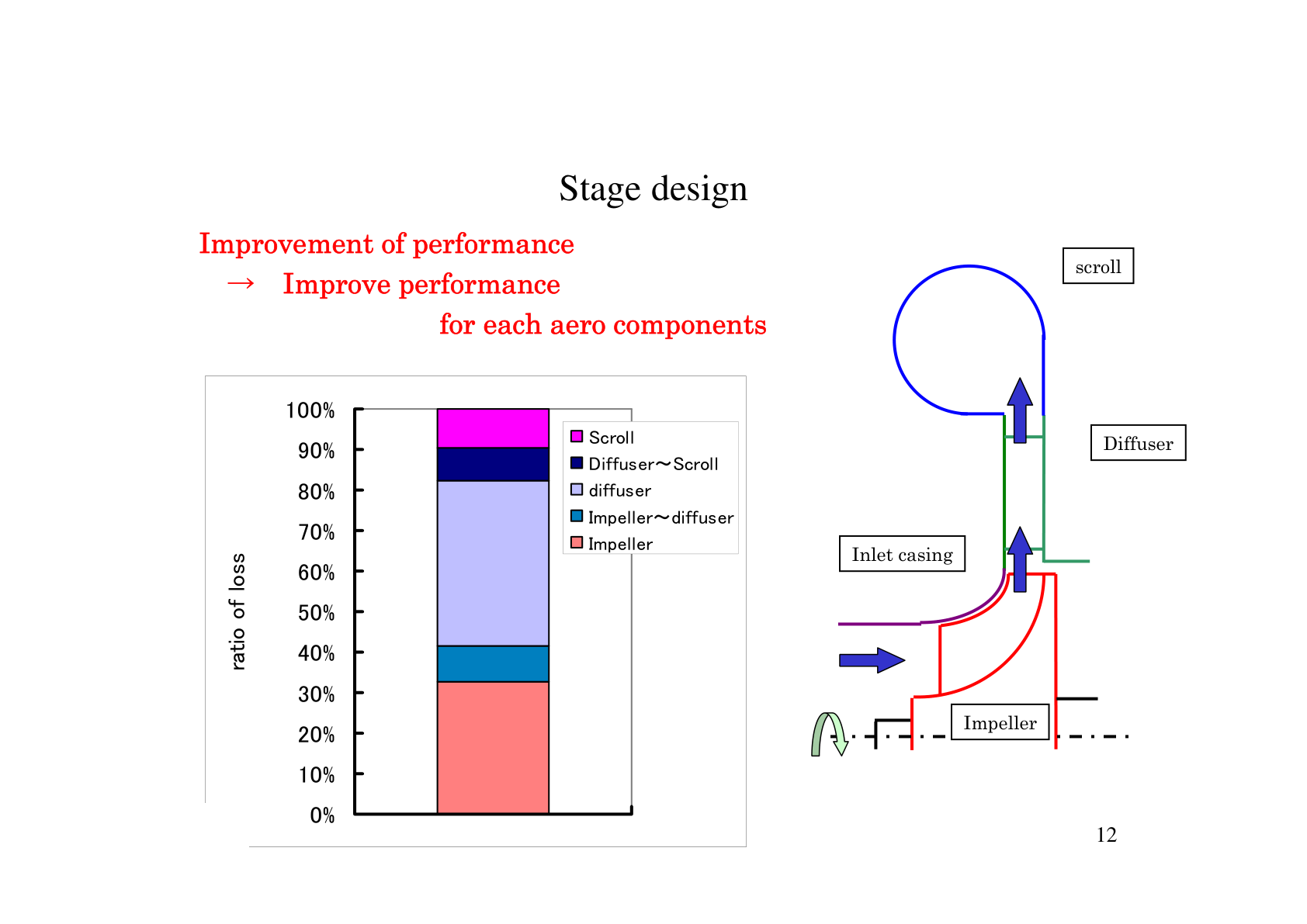
Stage design starts from the required pressure and flow. The designer distributes the total pressure rise across the impeller, diffuser and scroll — and each component generates its own share of losses. When performance drops, the loss distribution tells you where to look first: impeller fouling or erosion, diffuser fouling, or scroll distortion.
3. Impeller characteristics: flow cut and diameter
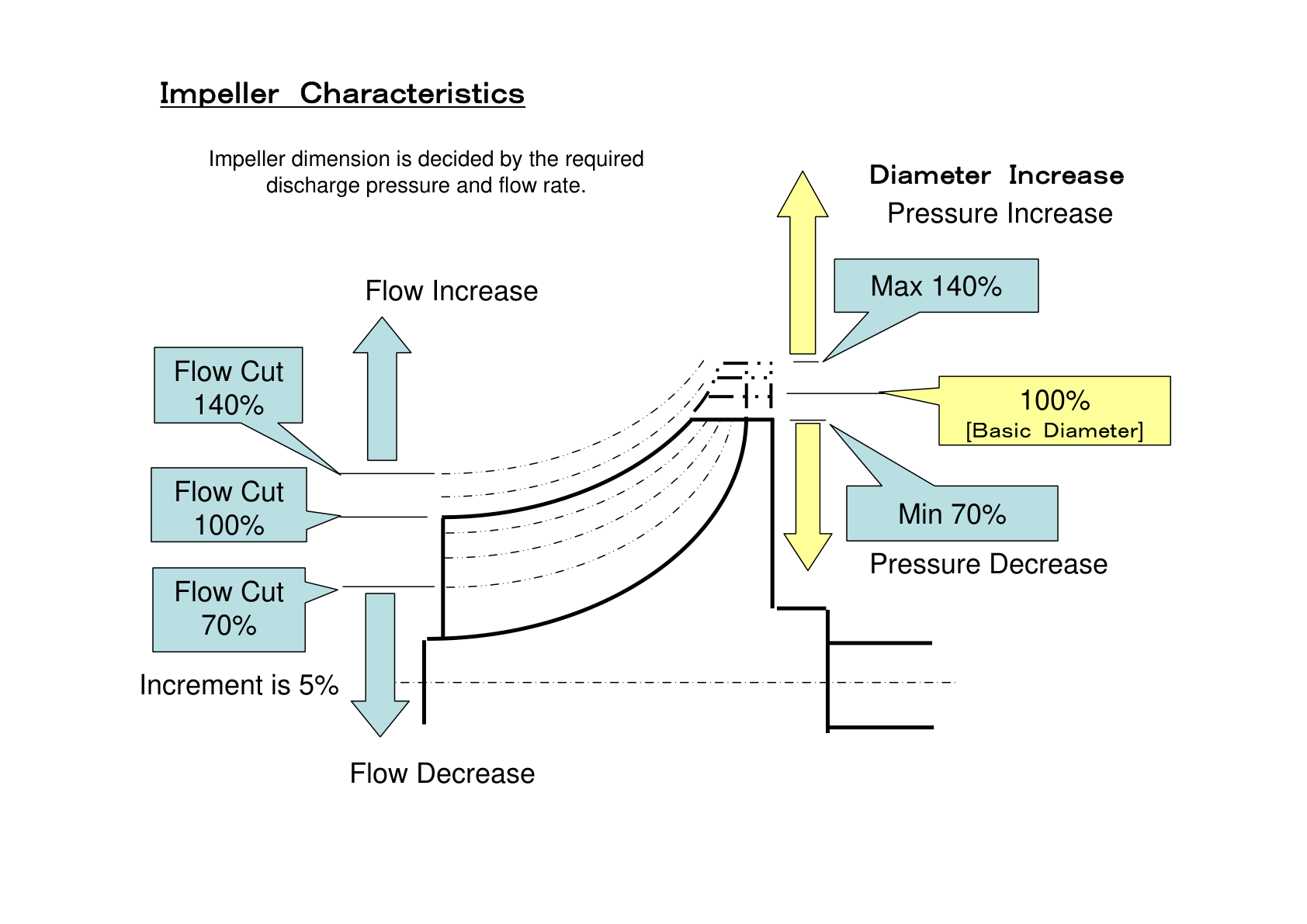
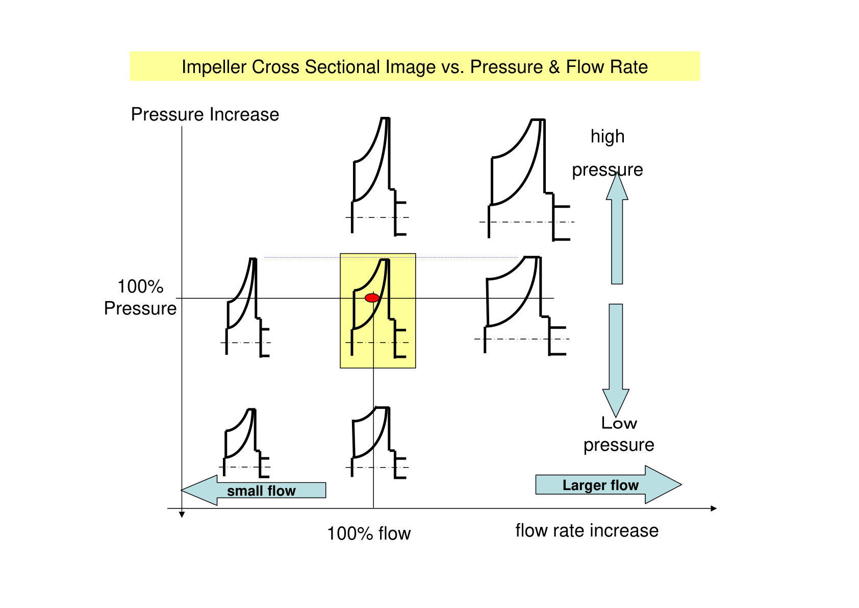
Impeller performance is shown as a characteristic curve. The training charts show how the curve shifts with flow cut — trimming or extending the flow path — in a typical range of 70% to 140% in roughly 5% steps, and with impeller diameter changes. This is why a replacement impeller must match the original geometry exactly: even small deviations move the operating point.
4. The inlet scroll: flow-cut range and evaluation
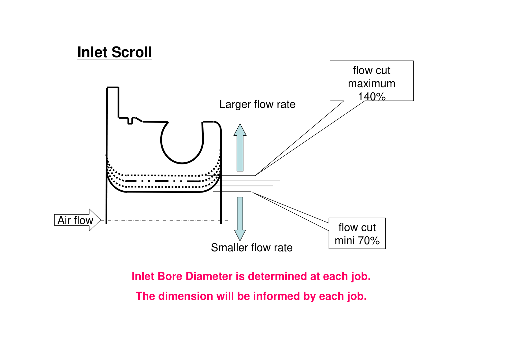
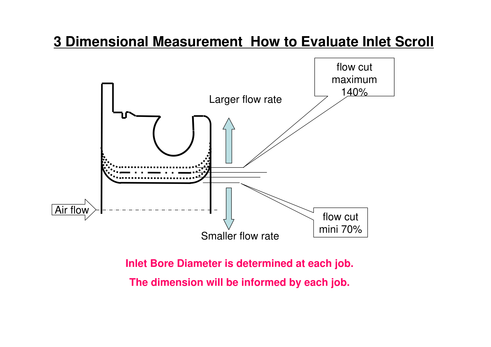
The inlet scroll feeds air to the first impeller. Its flow-cut range is typically max 140% / min 70%, and the inlet bore is set per project. Because the scroll is a complex casting, its quality cannot be judged with callipers — the evaluation is done with a 3D measuring system.
5. Why the inlet scroll is a critical component
The training material is explicit: the inlet scroll is the most critical component of the compressor, and it must be checked with 3D measuring systems. Its internal geometry decides how uniformly air enters the first impeller — errors here cost efficiency across the whole machine and eat into the surge margin.
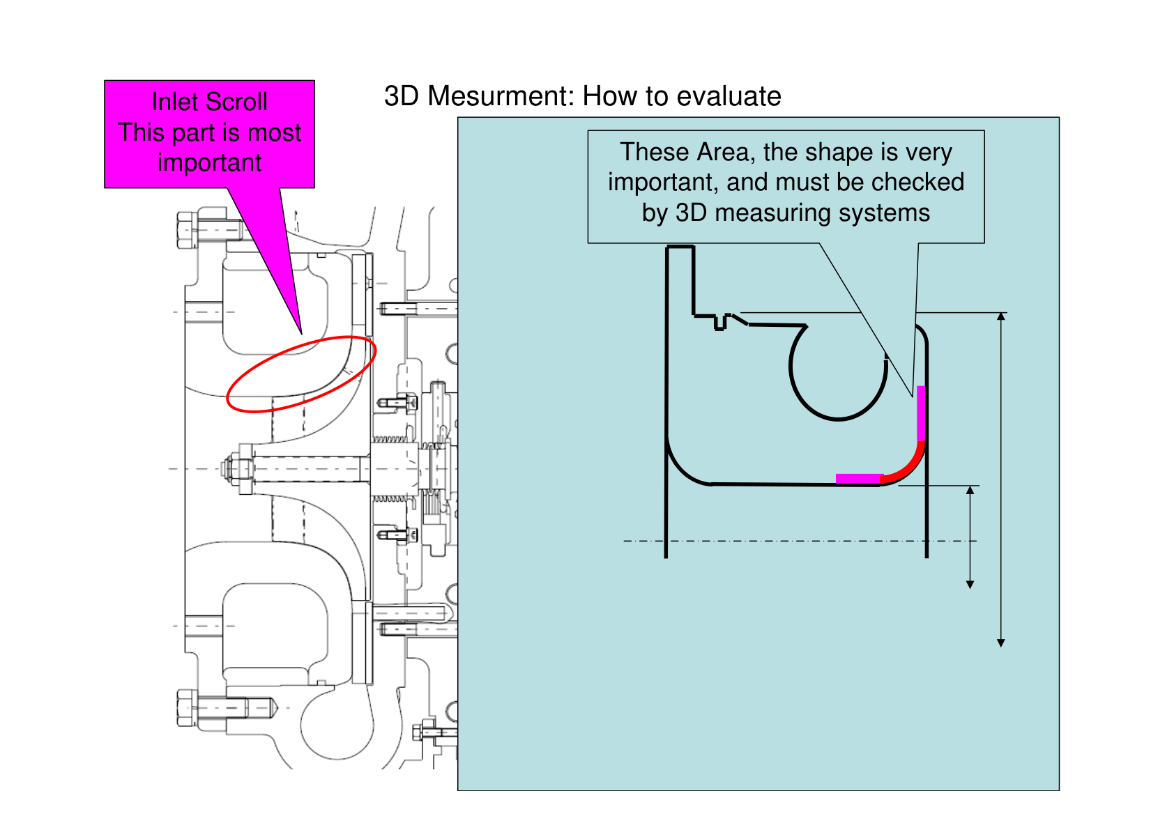
6. How to measure: sensor ball, X/Y/Z axes and CAD comparison
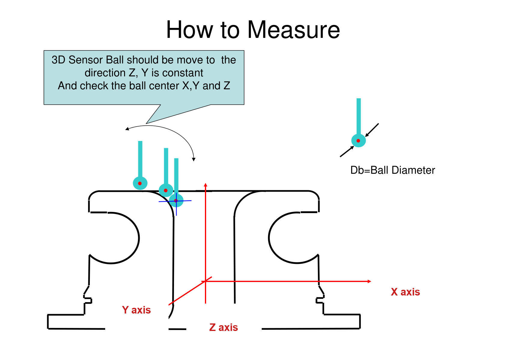
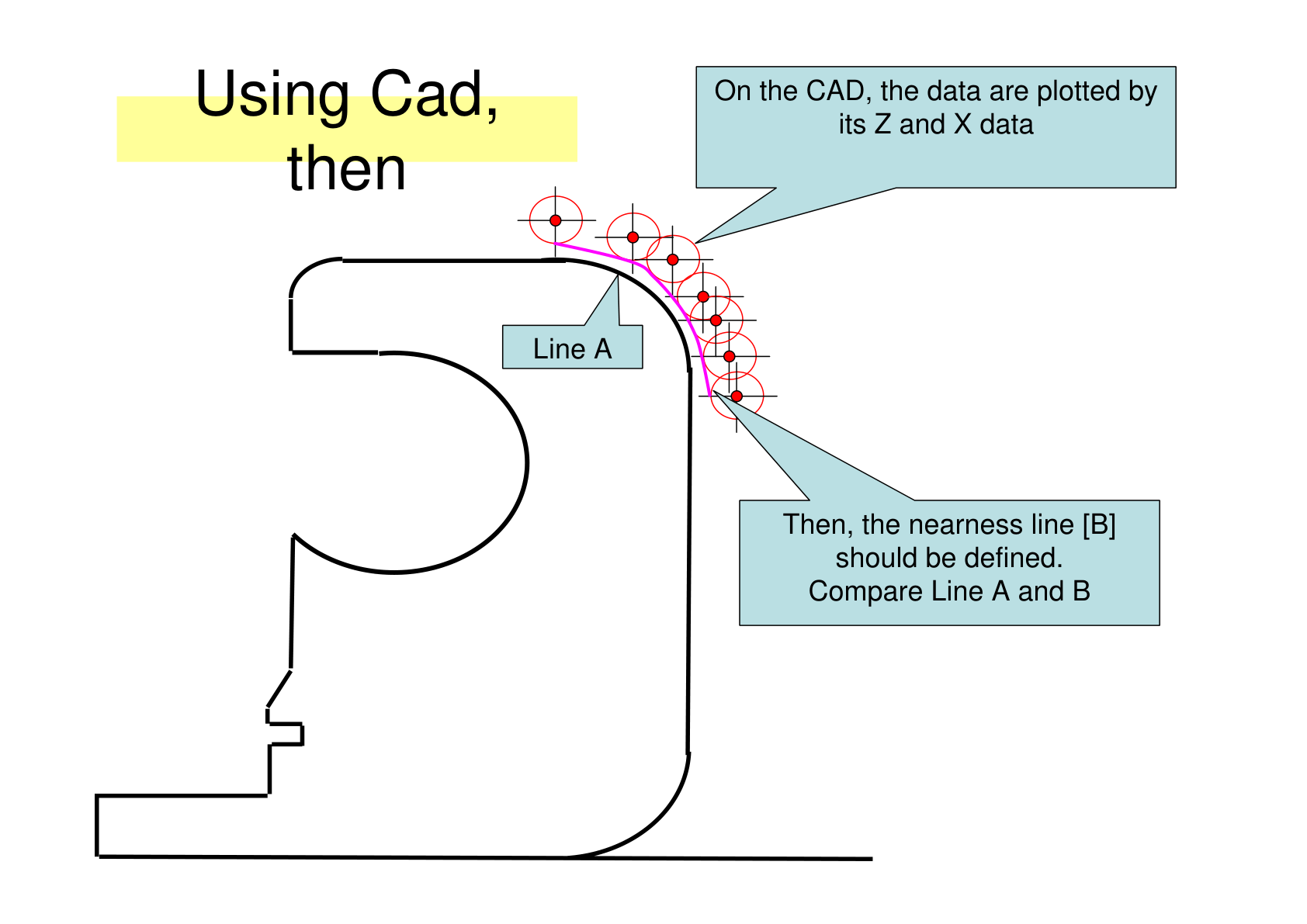
The measurement method uses a 3D sensor ball of known diameter (Db = ball diameter) traced along the scroll surface, with the position recorded on the X, Y and Z axes. The measured data is then plotted against the Z and X axes and compared with the CAD model — Line A vs Line B — to confirm that the actual scroll geometry matches the design.
What this means for your spare parts planning
Three practical takeaways for buyers and maintenance planners:
- The impeller decides the whole stage — order replacement impellers with dynamic balancing and verified geometry, not just “same look” parts. See our centrifugal compressor impeller page.
- Flow cut and inlet bore are project-specific — when you request a quote, send the model, serial number and stage data, exactly as described in our spare parts buying guide.
- During an overhaul, treat the scroll and stage geometry as inspection items — see how we apply this in a real IHI TRX160 overhaul case.
FAQ
What does the impeller do in a centrifugal compressor?
The impeller is the only component that adds energy to the gas: it converts shaft power into gas velocity. The diffuser and scroll then convert that velocity into pressure. Impeller condition therefore decides the performance of the whole stage.
What is flow cut on a compressor impeller?
Flow cut means trimming or extending the impeller flow path to shift the impeller characteristics. Typical training charts show a range of about 70% to 140%, in roughly 5% steps, used to match the machine to the required flow without changing the whole stage.
Why does the inlet scroll need 3D measurement?
The inlet scroll feeds the first impeller, so its geometry decides how uniformly air enters the machine. Its complex cast surface cannot be judged with callipers — it is verified with a 3D measuring system (sensor ball, X/Y/Z axes) and compared with the CAD model.
How Turbomax can help
Turbomax supplies replacement impellers, diffusers, scrolls and complete stage spare parts for IHI, Cameron, Atlas Copco and Hanwha centrifugal compressors — with dynamic balancing, dye penetrant check and 3D-verified geometry. Contact us for a fast quotation.
Spare parts by model
T2ATXATRATRET3ATRXTA3000TA6000TA9000TA11000MSG
Related reading: What maintenance does a centrifugal air compressor need? (A–E service grades)